No Products in the Cart

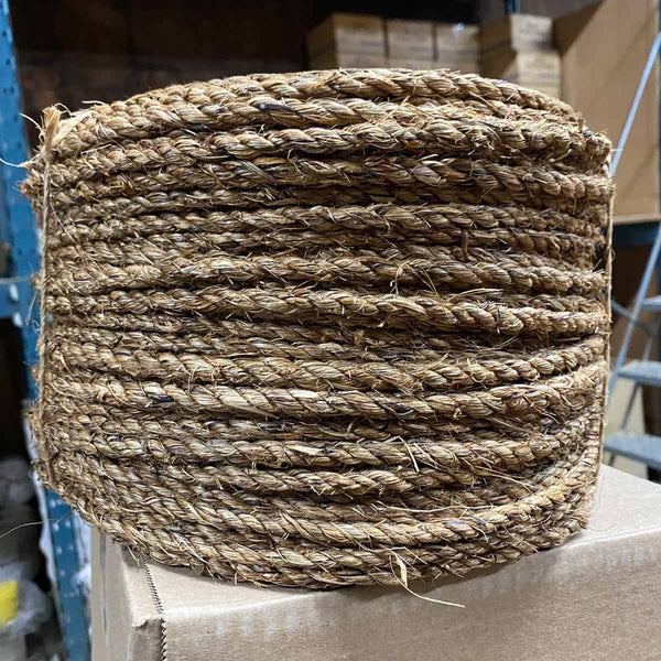
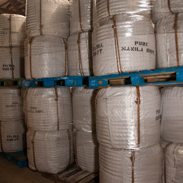
Manila rope, sometimes referred to as “hemp rope”, is manufactured from the strongest natural fibers available of the abaca plant grown in the Philippines. Manila rope provides high strength with very good resistance to abrasion and low stretch.
Manila rope is used in a wide range of industries including: